FAQ
Häufig gestellte Fragen


The problem may come from the “Arm Up” sensor (badly adjusted or defective), or from excessive slack on the Z arm (adjustment of prestress, section I in the customer file).
Change the P447 value to 128 for non-axial robots.
Adjust switch SW3-6 inside the pendant (this determines the communication speed).
The XQP connector at the end of the arm is missing or the 24V1 is missing.
Reset Flags using the PC2 robot software.
Reset Flags using the PC2 robot software. Make regular backups of your robots using the SEPRO editor. A robot without a PC option (DNC) can communicate with the PC Editor if the pendant cable on X4 is disconnected from the CPU board.
For all functional faults, check the power supply and control voltages, and particularly the 5V voltage on the back of the electronic boards rack (the voltage must be between 5.1V and 5.2V).
The CPU board needs to be replaced (the board manages axis displacements) Please use the Helpdesk contact form to contact our spare parts department
Recalibrate the touch screen by moving the switch in the pendant to position 3 and then follow the instructions given on the screen.
Position 9 : Pendant CAN active (CAN Robot and Speed driver CAN deactivated) Position A : Pendant CAN and speed driver CAN active (Robot CAN deactivated) Position B : Pendant CAN and Robot CAN active (Speed driver CAN deactivated)

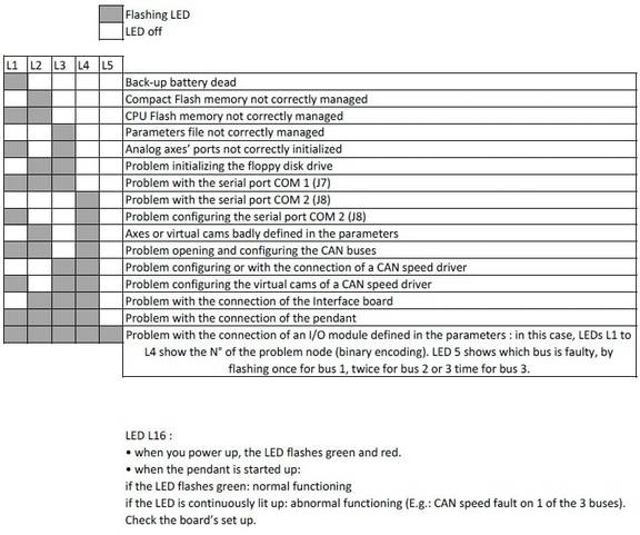
You can check the functioning using the troubleshooting LED’s : - Power up - Wait until the board is properly started up (about 2 minutes).
The problem may come from a short circuited sensor (XQP connector at the end of the Z arm, rotation sensors, etc.).
Make regular backups of your robots using the SEPRO editor.
Connect a wire mouse to the USB and restart the cabinet
Remember to regularly backup your robots on a USB stick. After swapping pendants between two robots for troubleshooting, each pendant must be returned to its original robot because the serial numbers are fixed on the pendant.